Uml Static Vs Dynamic Diagrams
Types of UML
UML can be divided into two broad categories:
A. Structural Diagrams
B. Behavioral Diagrams
A. Structural Diagrams
- Structural diagram is an important part of the UML.
- It represents the static aspect of the system and the static parts of the diagrams are represented by classes, interfaces, objects, components and nodes.
- Theses diagrams show the things and different objects in a system being modeled.
Following diagram shows the types of structural diagrams:
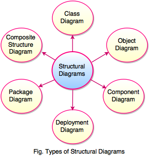
1. Class Diagram
- Class diagram is the main building block of any object oriented solution.
- Class diagram shows the classes in a system, attributes, relationships and operations of each class.
- It represents the object orientation of a system. So it is used for development purpose.
- Class diagram is the most widely used diagram at the time of system construction.
- Class diagram is used for data modeling.
- Class diagram shows the structure of the designed system at the level of classes and interfaces.
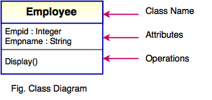
In the above figure, class diagram has three parts, represented with boxes.
- The top part contains name of the class <Employee>
- The middle part contains the attributes of the class <empid:Integer>, <empname:String>
- The bottom part contains the operations or methods of the class <Display()>.
A number of classes are identified and grouped together in a class diagram which helps to determine the static relations between them.
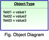
2. Object Diagram
- Object diagram is derived from class diagram, so the object diagrams are dependent upon class diagrams.
- This diagram represents an instance of a class diagram.
- Object diagram is used to render a set of objects and their relationships as an instance.
- It shows a snapshot of the detailed state of a system at a point in time.
- It is used to show how a system will look like at a given time, because there is data available in the objects.
- Object diagram is also used to explain complex relationships between objects.
Purpose of Object Diagram
Following are the purposes of Object diagram:
- The main purpose of object diagram is to implement object diagram practically.
- It represents an instance at a particular moment which is concrete in nature.
- Object diagram understands object behavior and their relationship from a practical perspective.
- It defines a static view of an interaction and object relationships of a system.
- These diagrams are used in forward and reverse engineering.
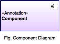
3. Component Diagram
- Component diagram is used to illustrate the structure of arbitrarily complex systems.
- It is used in Component-Based Development (CBD) to describe systems with Service-Oriented Architecture (SOA).
- This diagram has a higher level of abstraction than a Class diagram.
- It shows components, provided and required interfaces, ports and relationships between them.
- Component diagram consists of classes, interfaces or collaborations.
- It is used to visualize the implementation.
- It displays the structural relationship of components of a software system.
- The components are communicate with each other using interfaces and the interfaces are linked using connectors.
Usage of Component Diagram
Following are the uses of Component diagram:
- Component diagrams are used during the implementation phase of an application.
- Component diagram is used to describe the artifacts of a system.
- It constructs executable by using forward & reverse engineering and describes the organization & relationships of the components.
- These diagrams are used to model executables of an application and the database schema & system's source code.
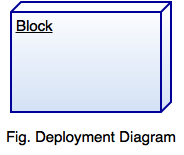
4. Deployment Diagram
- Deployment diagram is used to visualize the topology of the physical components of a system where the software components are deployed.
- It is used to describe the static deployment view of a system.
- These diagrams are used for describing the hardware components where software components are deployed.
- It helps to model the physical aspect of an object-oriented software system.
- It models the run-time configuration in a static view and visualizes the distribution of components in an application.
- It helps to model the physical aspect of an object-oriented software system.
Uses of Deployment Diagram
Following are the common uses of Deployment diagram:
- Deployment diagram is used to describe the physical components, their distribution and association.
- These diagrams are used to model the hardware topology of a system, embedded system, hardware details for a client/server system and distributed application.
- It is used for forward and reverse engineering.
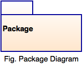
5. Package Diagram
- Package diagram is a namespace used to group together elements that are semantically related and might change together.
- These diagram shows the arrangement and organization of model elements in middle to large scale project.
- It can show both structure and dependencies between sub-systems or modules.
- Package diagram contains use cases to illustrate the functionality of a software system.
- It represents different layers of a software system to illustrate the layered architecture of a software system and compile time grouping mechanism.
- The dependencies between these packages can be adorned by labels or stereotypes to indicate the communication mechanism between the layers.
- It is used in large scale systems to picture dependencies between major elements in the system.
6. Composite Structure Diagram
- Composite structure diagram is a static structure diagram.
- It shows the internal structure of a class.
- These diagram visualizes the internal structure of a class or collaboration.
- It is a kind of the component diagram mainly used in modeling a system at micro point-of-view.
- These diagrams shows the configuration and relationship of parts that together perform the behavior of the containing classifier.
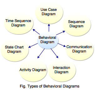
B. Behavioral Diagrams
- Behavioral diagram is used to describe how the objects interact with each other to create a functioning system.
- These diagrams shows how would happen in a system.
- It is used to visualize, specify, construct and document the dynamic aspects of a system.
Following diagram shows the types of structural diagrams:
1. Use Case Diagram
- Use case diagram represents a user goal which can be achieved by accessing the system or software application.
- These diagrams describes the relationships between the functionalities and their internal or external controllers. These controllers are known as Actors.
- It gives a graphic overview of the actors involved in a system, different functions needed by those actors and how these different functions are interacted.
Following are the components of Use Case Diagram.
| Components | Description |
|---|---|
 | It describes the interactions that take place between actors and IT systems during the execution of business processes. |
 | It represents the users of system, actors can actually be anything that needs to exchange information with the system. It may be people, computer hardware, other system etc. |
 | It represents a connection between an actor and a use case. It indicates that an actor can carry out a use case. |
 | It is a relationship between two use cases. It specifies how the behavior for the inclusion use case is inserted into the behavior defined for the base use case. |
 | It specifies how the behavior of the extension use case can be inserted into the behavior defined for the base use case. |
 | It represents inheritance relationship between model elements of same type. |
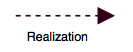 | It is a relationship between a specification and its implementation. It is used to model stepwise refinement, optimizations, transformations, templates, model synthesis, framework composition etc. |
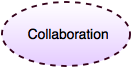 | It describes a structure of collaborating elements. |
2. Sequence Diagram
- Sequential diagram is used to show the interactions between objects represented as lifelines in a sequential order.
- It models the collaboration of objects based on a time sequence.
- These diagrams shows how the objects interact with others in a particular scenario of a use case.
- It is an interaction diagram which shows a message sequence chart.
- It shows object interactions arranged in time sequence.
Following are the components of Sequence Diagram:
| Components | Meaning | Description |
|---|---|---|
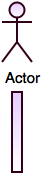 | Actor | It represents role played by human users, external hardware or other subjects. |
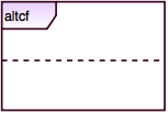 | Alternative Combined Fragment | It defines an expression of interaction fragments. Using combined fragment the user will be able to describe a number of traces in a compact and concise manner. |
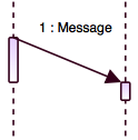
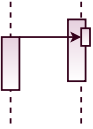
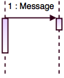 | Call Message / Send Message / Sequence Message | It defines a particular communication between lifelines of an interaction. It represents an invocation of operation of target lifeline. |
 | Concurrent | It represents a session of concurrent method invocation along an activation. It's placed on top of an activation. |
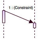
 | Constraint | It represents a condition or restriction expressed in natural language text or in a machine readable language for the purpose of declaring some of the semantics of an element. |
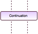 | Continuation | It is a syntactic way to define continuations of different branches of an Alternative Combined Fragment. It represents intermediate points in a flow of control. |
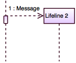 | Create Message | It defines a particular communication between Lifelines of an interaction. It represents instantiation of lifeline. |
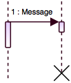 | Destroy Message | It defines a particular communication lifelines of an interaction. It represents the request of destroying the lifecycle of target lifeline. |
 | Duration Constraint | It defines a constraint which refers to a DurationInterval. |
 | Duration Message | It defines a particular communication between lifelines of an interaction. It shows the distance between two time instants for a message invocation. |
 | Found Message | It is a message where the receiving event occurrence is known, but there is no sending event occurrence. |
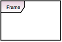 | Frame | It represents interaction which is a unit of behavior that focuses on the observable exchange of information between ConnectableElements. |
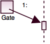 | Gate | It is a connection point for relating a message outside an interaction fragment with a message inside the interaction fragment. |
 | Lifeline | It represents an individual participant in the interaction. |
 | Lost Message | It is a message where the sending event occurrence is known, but there is no receiving event occurrence. |
 | Note | It gives the ability to attach various remarks to elements. |
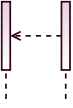 | Return Message | It defines a particular communication between lifelines of an interaction. |
 | Recursive Message | It is a kind of message that represents the invocation of message of the same lifeline and it's target points to an activation on top of the activation where the message was invoked from. |
 | Reentrant Message | It points to an activation on top of another activation. |
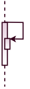
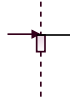
 | Self Message | It represents the invocation of message of the same lifeline. |
 | Time Constraint | It defines a constraint which refers to a time interval. |
3. Communication Diagram
- Communication diagram is similar to sequence diagram, the only difference is that, it focuses on the messages passed between objects.
- It illustrates the dynamic view of the system.
- It is designed to emphasize the structural organization of the object's send and receive messages.
- It represents a combination of information from Class, Sequence, and Use Case diagrams describing both the static structure and dynamic behavior of a system.
- It models the dynamic behavior of the use case.
Following are the components of Communication Diagram:
| Components | Meaning | Description |
|---|---|---|
| | Actor | It represents role played by human users, external hardware or other subjects. |
 | Lifeline | It represents an individual participant in the interaction. |
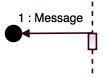
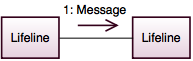
 | Message / Send Message / Sequence Message / Call Message | It defines a particular communication between lifelines of an interaction. |
 | Return Message | It represents the pass of information back to the caller of a corresponded former message. |
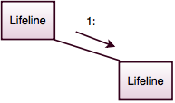 | Link | It is a tuple with one value for each end of the association, where each value is an instance of the type of the end. |
| | Note | It gives the ability to attach various remarks to elements. |
| | Frame | It represents interaction which is a unit of behavior that focuses on the observable exchange of information between ConnectableElements. |
4. State Diagrams
- State diagrams are known as State Chart Diagrams or State Machine Diagrams.
- These diagrams are useful to describe the behavior of objects which act differently according to the state they are in at the moment.
- It shows the different states of an entity and describes how an entity responds to various events by changing from one state to another.
- It is designed to illustrate how the graphic elements can be assembled into diagrams.
- It provides cross references where detailed information about the semantics and concrete notation for each element can be found.
Following are the components of State Machine Diagram:
| Components | Meaning | Description |
|---|---|---|
 | Choice | It realizes a dynamic conditional branch and allows splitting of transitions into multiple outgoing paths. |
 | Deep History | It represents the most recent active configuration of the composite state that directly contains the pseudostate. |
 | Shallow History | It represents the most recent active substate of its containing state. |
 | Entry Point | It represents an entry point of a state machine. |
 | Exit Point | It represents an exit point of a state machine. |
 | Fork and Join | Fork serve to split an incoming transition into two or more transitions terminating on orthogonal target vertices. Join serves to merge several transitions emanating from source vertices in different orthogonal regions. |
 | Final State | It specifies that the enclosing region is completed. |
 | Initial Pseudo State | It represents a default vertex that is source for a single transition to the default state of a composite state. |
 | State | It is a situation during which some invariant condition holds. |
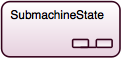 | Submachine State | It specifies the insertion of the specification of a submachine state machine. |
 | Terminate | It represents the execution of the state machine is terminated. |
 | Transition | It represents a direct relationship between a source vertex and a target vertex. |
5. Activity Diagrams
- Activity diagram is related to program flow plans or flow charts are used to illustrate the activities.
- It allows to think functionally and can be developed in various degrees of detail.
- These diagrams are the graphical representations of workflows of stepwise activities and actions with support for choice, iteration and concurrency.
- It represents the flow from one activity to another activity and can be described as an operation of the system.
- It deals with all types of flow controls by using different elements like fork, join etc.
- It is used to show message flow from one activity to another.
Following are the components of Activity Diagrams:
| Components | Meaning | Description |
|---|---|---|
 | Activity | It specifies the coordination of executions of subordinate behaviors using a control and data flow model. |
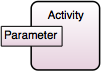 | Activity Parameter Node | It is an object node at the beginning and end of flows which accept inputs to an activity and provide outputs from the activity, through the activity parameters. |
 | Action | It represents a single step within an activity. |
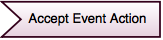 | Accept Event Action | It is an action that waits for the occurrence of an event meeting specified condition. |
| | Activity Final Node | It stops all flows in the activity. |
| | Decision Node | It accepts tokens on an incoming edge and presents them to multiple outgoing edges. |
 | Exception Handler | It is an element which specifies a body to execute in case the specified exception occurs during the execution of the protected node. |
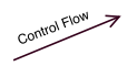 | Control Flow | It is an edge that starts an activity node after the previous one is finished. |
6. Interaction Diagram
- Interaction diagram is a derived form of the Activity diagram where the nodes are the interactions or interaction occurrences.
- These diagrams describes the interactions where messages and lifelines are hidden.
- UML 2.4 requires branching and joining of branches in interaction overview diagrams to be properly nested.
- Interaction diagram is more restrictive compared to activity diagrams and could be quite difficult to obey.
- The lifelines and messages do not appear in this overview level.
- It is used to describe some type of interactions between different elements in the model.
- The main purpose of interaction diagram is to capture dynamic behavior of a system and describe message flow in the system, structural organization of the objects & interaction between objects.
- These diagrams are used to understand the message flow and the structural organization.
- It is used for forward & reverse engineering and to model flow control by time sequence & structural organizations.
Following are the components of Interaction Diagrams:
| Components | Meaning | Description |
|---|---|---|
| | Activity Final Node | It stops all flows in the activity. |
| | Control Flow | It is an edge that starts an activity node after the previous one is finished. |
| | Constraint | It represents a condition or restriction expressed in natural language text or in a machine readable language for the purpose of declaring some of the semantics of an element. |
| | Decision Node | It accepts tokens on an incoming edge and presents them to multiple outgoing edges. |
| | Fork and Join | Fork serve to split an incoming transition into two or more transitions terminating on orthogonal target vertices. Join serves to merge several transitions emanating from source vertices in different orthogonal regions. |
| | Initial Node | It represents a default vertex that is source for a single transition to the default state of a composite state. |
 | Interaction | It is a unit of behavior that focuses on the observable exchange of information between ConnctableElements. |
| | Note | It gives the ability to attach various remarks to elements. |
7. Time Sequence Diagram
- Time sequence diagram focuses on timing constraint.
- It is a special form of sequence diagram.
- These diagrams focuses on conditions changing within and between lifelines along a linear time axis.
- It describes behavior of both individual classifiers and interactions of classifiers.
- It is used to explore the behaviors of objects throughout a given period of time.
- There is only difference between timing diagram and sequence diagram is that the axes are reversed so that the time is increased from left to right.
Following are the components of Time Sequence Diagrams:
| Components | Meaning | Description |
|---|---|---|
| | Constraint | It represents a condition or restriction expressed in natural language text or in a machine readable language for the purpose of declaring some of the semantics of an element. |
| | Note | It gives the ability to attach various remarks to elements. |
| | Frame | It represents interaction which is a unit of behavior that focuses on the observable exchange of information between ConnectableElements. |
Source: https://www.tutorialride.com/software-architecture-and-design/uml-types.htm
Posted by: moczygembarozannenoes.blogspot.com

Posting Komentar untuk "Uml Static Vs Dynamic Diagrams"